SUPPORT
HAYMAKER-S
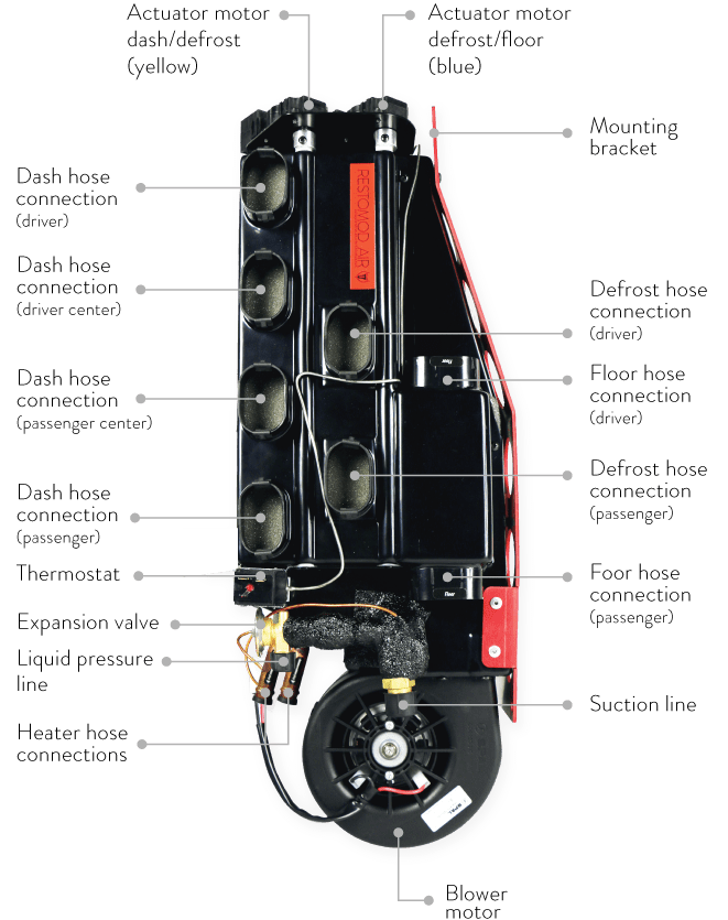
HAYMAKER - S FUNCTIONS
CHANGING AIR POSITIONS
The Haymaker – S allows for blending air positions and temperatures. When turning mode knob clockwise, air will blend from dash to defrost by activating the yellow servo motor. When continuing the rotation of the knob clockwise, the air will blend from defrost to floor by activating the blue servo motor.
CHANGING AIR TEMPERATURES
When turning temp knob clockwise, temperature will increase from cold to hot. Like modern vehicles, the compressor is active in all mode positions to allow temperature blending by adding heat with the temperature knob. Compressor is in full heat position.

PLANNING INSTALL
If your vehicle has been or is being modified, some procedures will need to be adjusted to fit your particular application. Read below before cutting/drilling. Since this is a custom installation that will vary based on your particular vehicle, many of our procedures can be viewed as suggestions. Your personal preferences will play a major role in the actual installation.
LOCATION OF THE UNIT
The Haymaker – S is designed for vehicles that have “flat /shaved/smoothed” firewalls. If you have not done this you might want to make a firewall plate before starting the install.
-
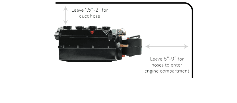
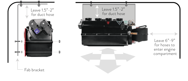
– leave a min. of 1.5” – 2” above unit for dash and defrost duct hose connections
-
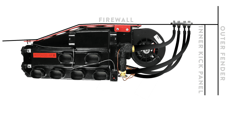
– leave a min. of 6“ – 9” right of the unit for a/c and heater hoses to enter the engine bay
-
– keep in mind ECU wires are designed to mount near the a/c unit
-
– make sure unit is level
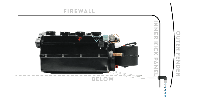
LOCATION OF THE DRAIN TUBE
Condensation forms when the compressor is active. Water exiting the evaporator uses gravity to evacuate. Water does not travel upwards.
-
– location of the drain tube hole must be below the unit
-
– use the supplied grommet and 90° elbow to create a tight seal
LOCATION OF THE HOSES TO ENGINE COMPARTMENT
-
– the Haymaker – S has heater and a/c connections
-
– use bulkhead plate as a drill template
-
– if using grommets: seal around hoses tightly to prevent engine/outside air & moisture entering the cabin
-
– when tightening fittings, make sure to use a backup wrench
-
– do not overtighten fittings (o-rings will crush or tear)
-
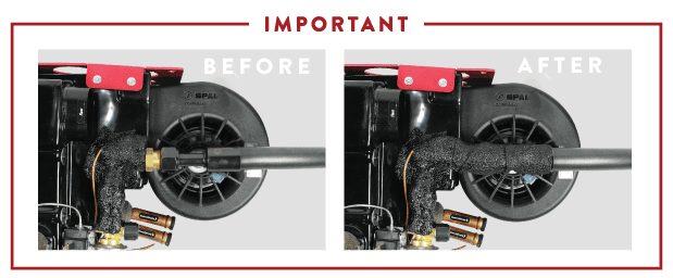
– after attaching hoses to evaporator, apply refrigerant tape to hose fittings on the evaporator to keep condensation from dripping on passenger floor board
-
– We have supplied fittings that work for most applications but if you need a different fitting, let’s swap. Give us a call.
While bulkhead plates create a visually appealing connection, they are important because they create a positive seal from engine bay conditions such as: moisture, heat and fumes. If you are not using a bulkhead, make certain to seal around hoses and use grommets to avoid premature failure caused by vibrations and friction. Seal all holes/seams or anything else that will allow engine/outside air to enter the cabin. Failing to do so will prevent a/c unit to perform at it’s highest ability.
LOCATION OF THE ECU
-
– ECU must be mounted near the unit with the supplied self tapping screws
Do not extend wires on (output) harness. Doing this will change resistance valves and will not allow your unit to function properly.
LOCATION OF THE CONTROLS
-
– locate a spot that looks killer but also functionable
-
– before cutting, make certain wires will connect to the ECU location
-
– make sure dash cavity will allow for control depth when mounted
-
– make sure nothing will interfere with control function
LOCATION OF THE DEFROST
When running defrost ducting, make certain to cycle the windshield wipers. Duct hose can be damaged by moving wiper arms.
-
– use supplied zip ties to secure duct hose to unit and defrost
LOCATION OF THE FLOOR DUCTS
The Haymaker – S is designed for large vehicles so we have provided 2 floor heat dumps. Heat is non-directional so location isn’t that important just make sure the air is pointed towards driver & passenger footwell. Kick panel areas are prime locations for heat dumps.
-
– use the supplied self tapping screws to attach to vehicle
-
– use supplied zip ties to secure duct hose to unit + floor ducts
LOCATION OF VENTS
-
– plan two vents for the driver and two vents for the passenger
-
– vents must be mounted where the air will be felt on passengers so odd locations such as kick panels are not ideal
-
– use supplied zip ties to secure duct hose to unit and vents
The location of a/c vents are the single most important decision to be made during planning & install. Remember, a/c IS directional. Placement of vents is critical to comfort for driver & passenger. The vent must be close to occupant or they will not be cool & comfortable.
MOUNTING
The mounting bracket allows for you to mount your unit flush with the inside smoothed/shaved/flat firewall.

FIREWALL MOUNTING
The most common place to mount the Haymaker – S is on the firewall behind the glovebox opening. Use one of the options to mount our multi mount bracket system.
CUSTOM COWL MOUNTING
In some situations, installers do not want to mount to a painted firewall. We recommend mounting from the inner cowl area found on some vehicles. Build a bracket that will “hang” the Haymaker – S from above and secure from side to side movement. More than one bracket will be needed.
DRAIN TUBE
It’s crucial the drain tube is angled down for water to drain – water flows down!
FIREWALL
Locate the drain nipple on the Haymaker – S. Drill a 3/4” hole for the drain tube below the drain nipple. Attach 1/2” drain tube to evaporator nipple and run through the drilled hole. Use the supplied grommet and 90° elbow for the drain tube to exit.
KICK PANEL
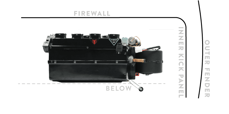
Most custom installers will not want the water exit to be on the firewall and choose the passenger kick panel instead. Make sure water actually exits the kick panel area and it does not collect in the cavity between inner kick panel and outer fender.
HOSES
FIREWALL WITH BULKHEAD/GROMMETS
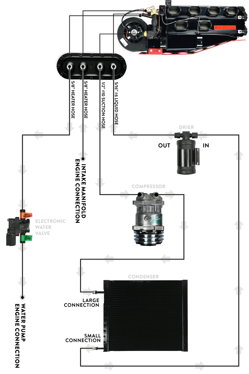
Cut supplied hoses to length needed. The supplied a/c + heater fittings are for interior connections because we assume you bought one of our badass bulkheads. Use supplied large zip ties to secure hoses.
KICK PANEL WITH BULKHEAD/GROMMETS
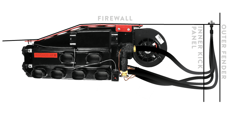
Some installers choose to run hoses in the far fender area via the inner kick panel. Additional length hoses will be needed (not supplied.) You will have 2 seals when going through kick panel. Use supplied large zip ties to secure hoses.
IMPORTANT
Make sure you wrap the #10 suction hose fitting on the Haymaker – S with refrigerant tape so condensation does not drip on the passenger floor board.

WATER VALVE
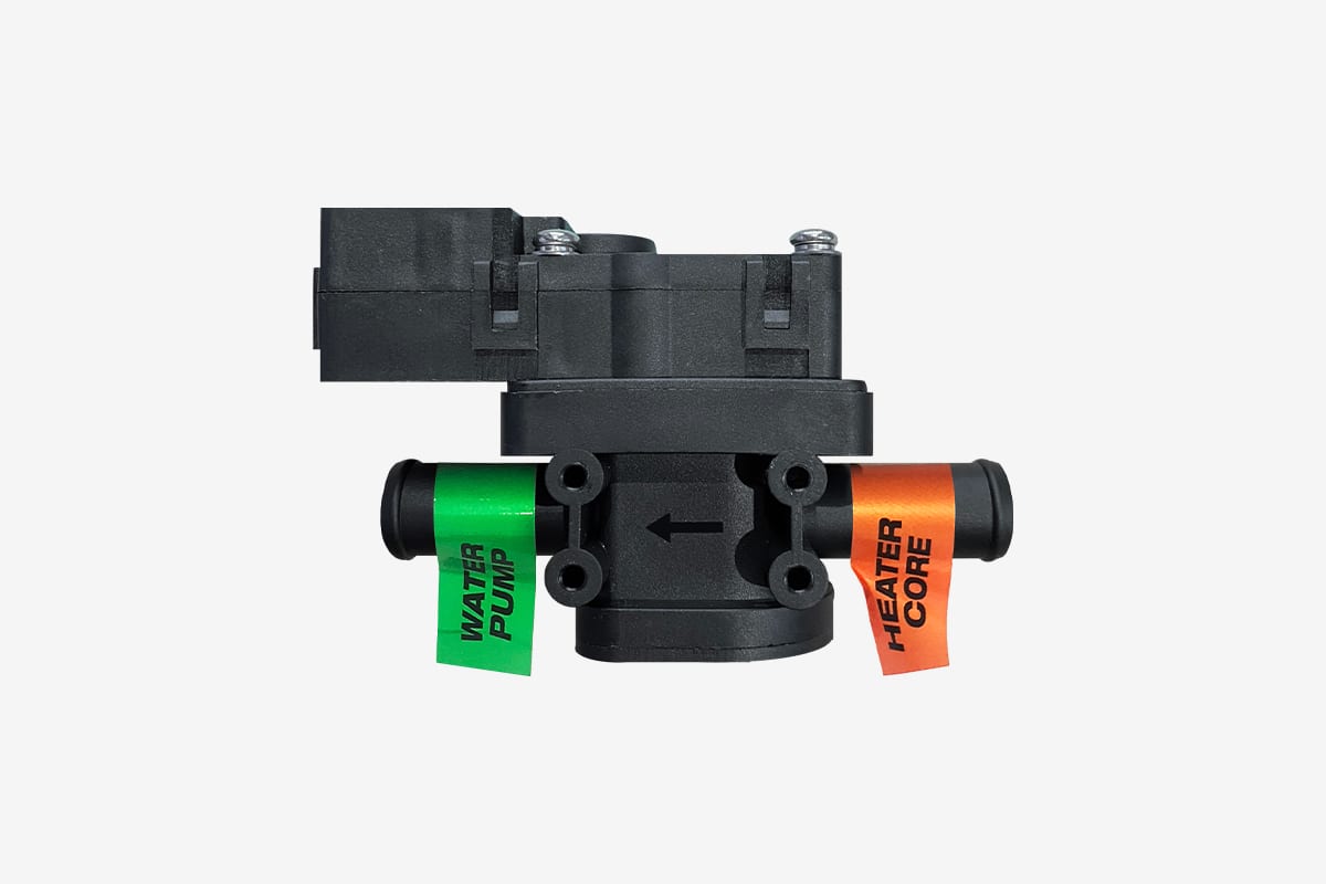
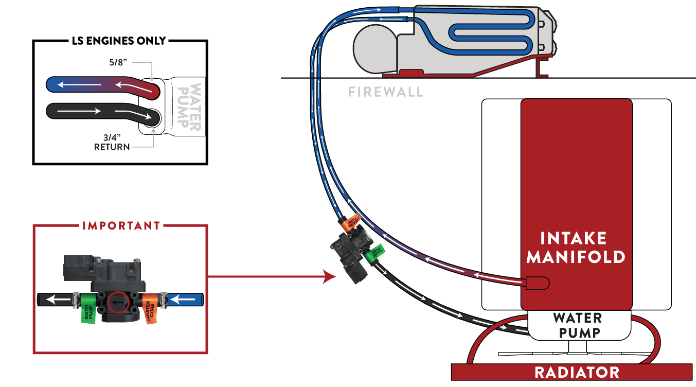
Make sure the water valve is positioned correctly. The water valve is a directional valve and should be installed with the arrow pointing towards the water pump. If the water valve is connected to the incorrect hose, it allows water to circulate through the system via the heater core overpowering the cooling effect of the a/c coil. Make certain the water valve goes to the water pump!
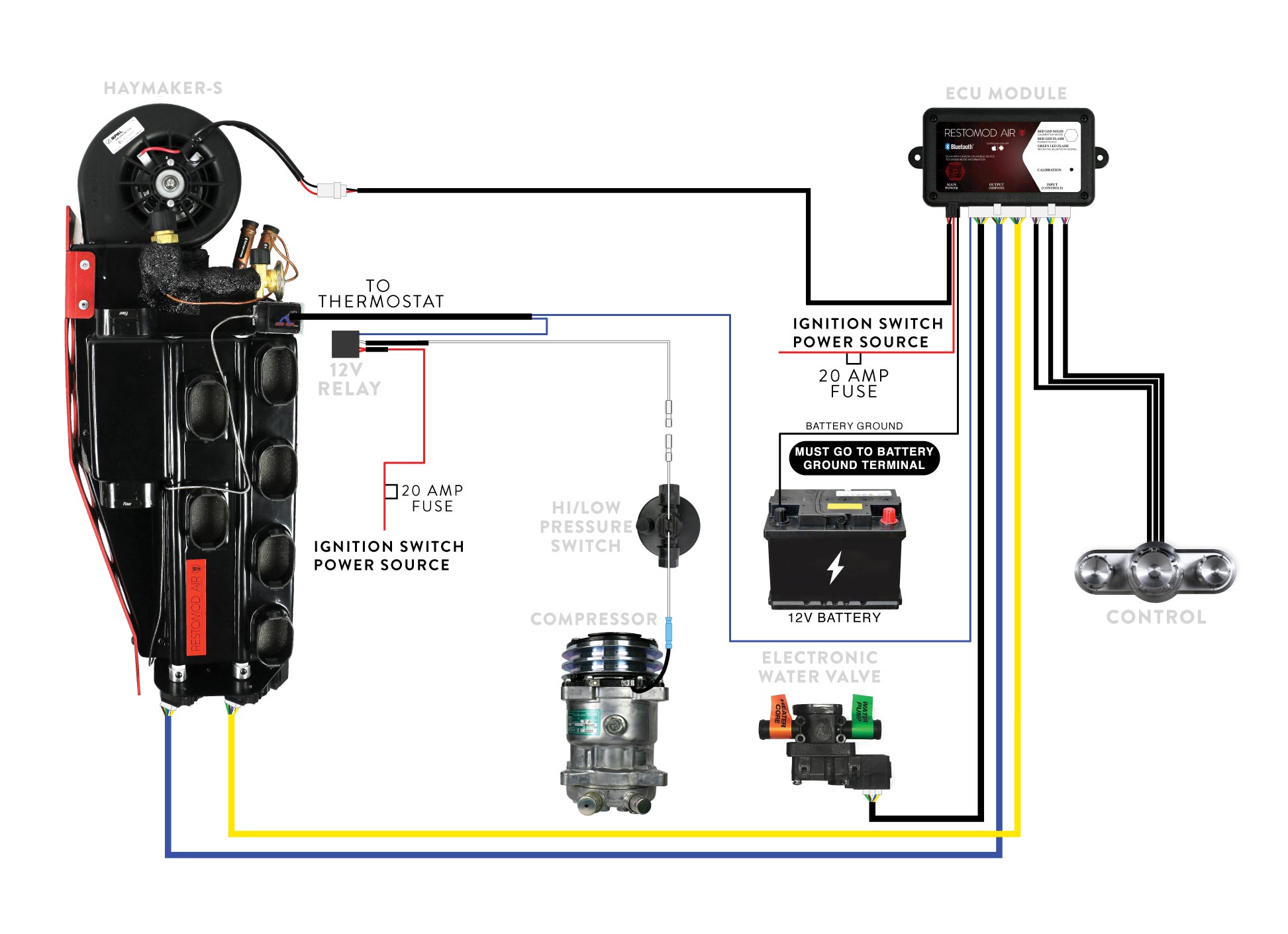
WIRING
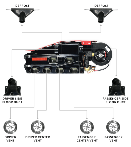
DEFROST + FLOOR DUCTS + VENTS
Use supplied zip ties to secure duct hose to defrost and vents. Cut duct hose to length needed. When cutting duct hose pull taut. Hose will stretch in summer months and possibly sag effecting the air flow.
ENGINE COMPARTMENT
PLANNING INSTALL
LOCATION OF THE CONDENSER
Condenser is purchased seperate. Make sure you have the largest possible size condenser for your vehicle. Surface area is important for maximum cooling. Rule of thumb is condenser size matches the “finned” area of the radiator.
-
– condenser needs to be mounted in a location where hoses can reach
-
– should be within 1” from radiator without touching
-
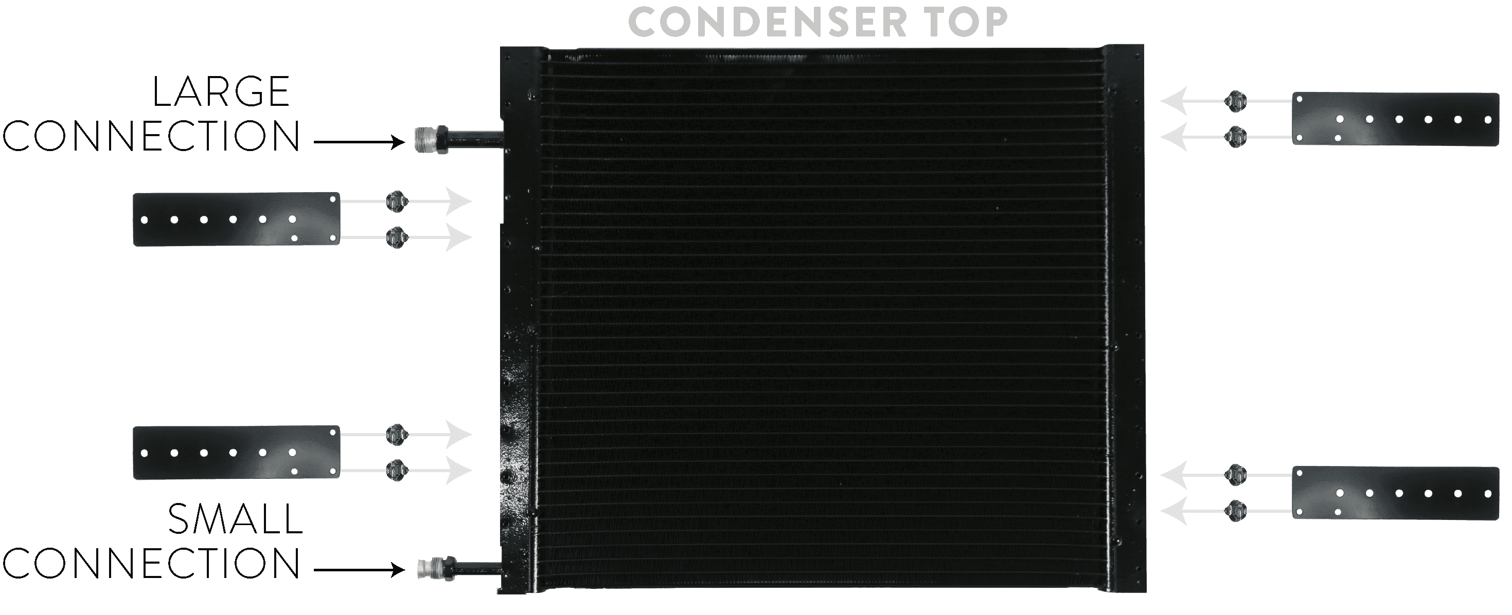
– condenser has 2 fitting connection: larger #8 connection on top, smaller #6 on bottom.
Failure to mount condenser with large fitting on top will result in system functioning incorrectly.
You can not lay down condenser flat/parallel to the ground. The oil within the system is heavier & thicker than refrigerant gas. The gas separates leaving the oil trapped in the condenser, ultimately starving the compressor of lubrication.
LOCATION OF THE DRIER
-
– drier needs to be mounted in a location where hoses can reach. Keep in mind refrigerant hoses from condenser & evaporator must connect to it.
-
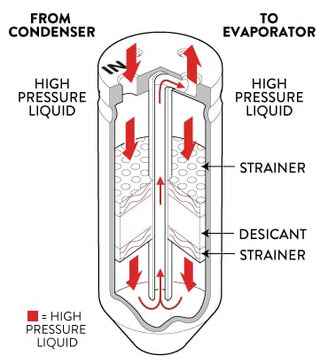
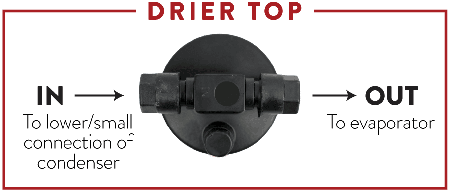
– drier mounts vertical with connections on top. Threaded connection labeled “IN” will connect to the lower connection of the condenser.
-
– do not leave drier open longer than a couple minutes. Doing so will require the drier to be replaced.
-
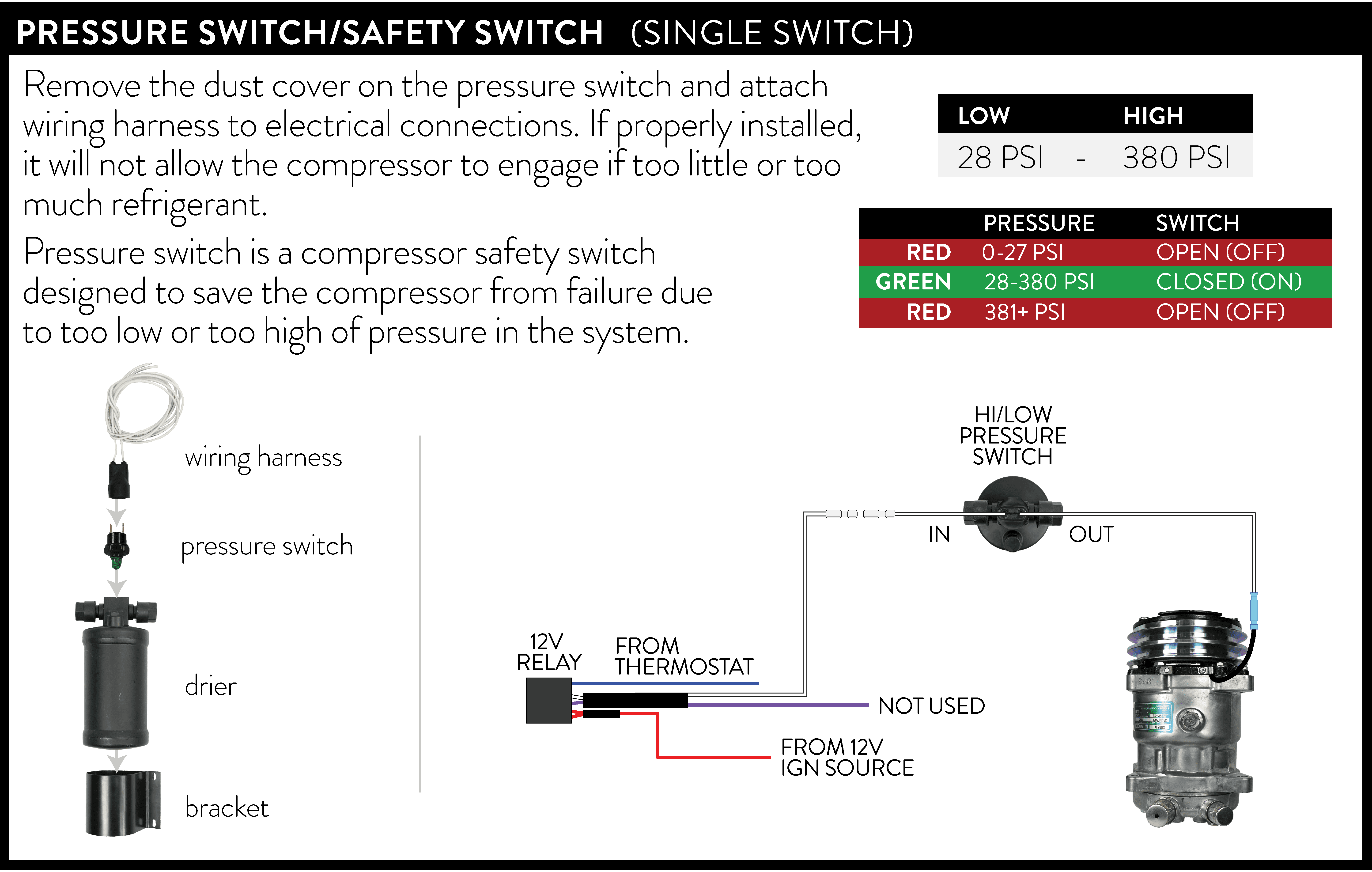
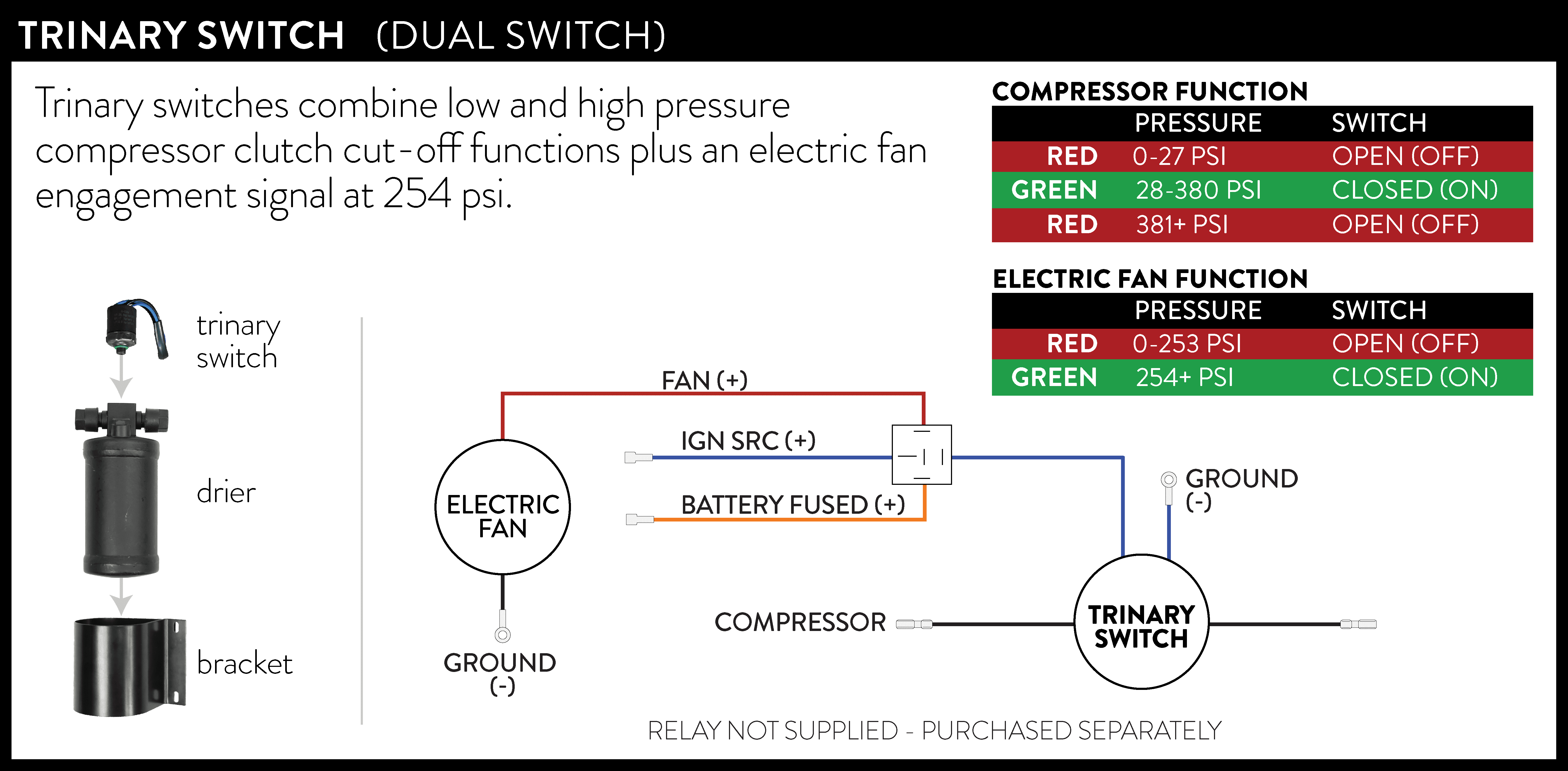
– the drier has a location for the pressure switch/trinary switch to thread into.
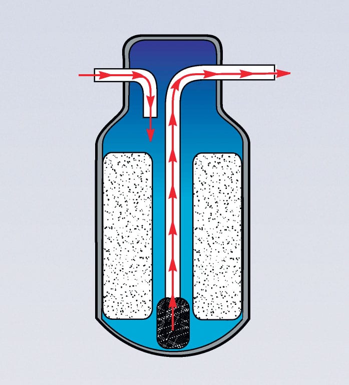
Receiver/driers are located in the high-pressure section of the system, usually in the plumbing between the condenser outlet & the expansion valve inlet, although some may be connected directly to the condenser.
They serve 3 very important functions:
1. They act as a temporary storage container for oil & refrigerant when neither are needed for system operation (such as during periods of low cooling demand). This is the “receiver” function of the receiver/drier.
2. They trap very small debris that may be inside the a/c system.
3. They contain desiccant. The desiccant is used to absorb moisture that may have gotten inside the a/c system during manufacture, assembly or service. Moisture can get into the a/c components from humidity in the air. This is the “drier” function of the receiver/drier.
Damage can occur if there is excessive moisture inside an a/c system. It can cause corrosion, as well as possibly degrade the performance of the compressor’s lubricating oil.
The receiver/drier should be replaced any time the system is opened for service, and most compressor warranties require it. The desiccant is only capable of absorbing a certain amount of moisture, and when the inside of the system and/or the receiver/drier are exposed to the atmosphere, the desiccant can become very quickly saturated from humidity in the air. If this occurs, the desiccant is no longer eective, and will not provide future protection. Additionally, the filter inside the receiver/drier could be restricted by debris that may have been inside the system. This could diminish refrigerant and oil flow.
LOCATION OF THE COMPRESSOR
Use installation instructions provided by your engine bracket manufacturer.
-
– Most brackets mount compressors either passenger or driver side.
-
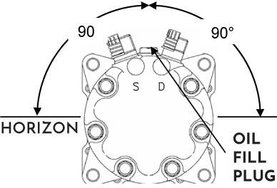
– Compressor fittings cannot be mounted with fittings downward
LOCATION OF THE HOSES
– make certain hoses have enough slack when connecting to compressor so that fittings do not prematurely fatigue w/engine vibrations
– make certain hoses are secured with supplied clamps so hoses don’t rub against objects
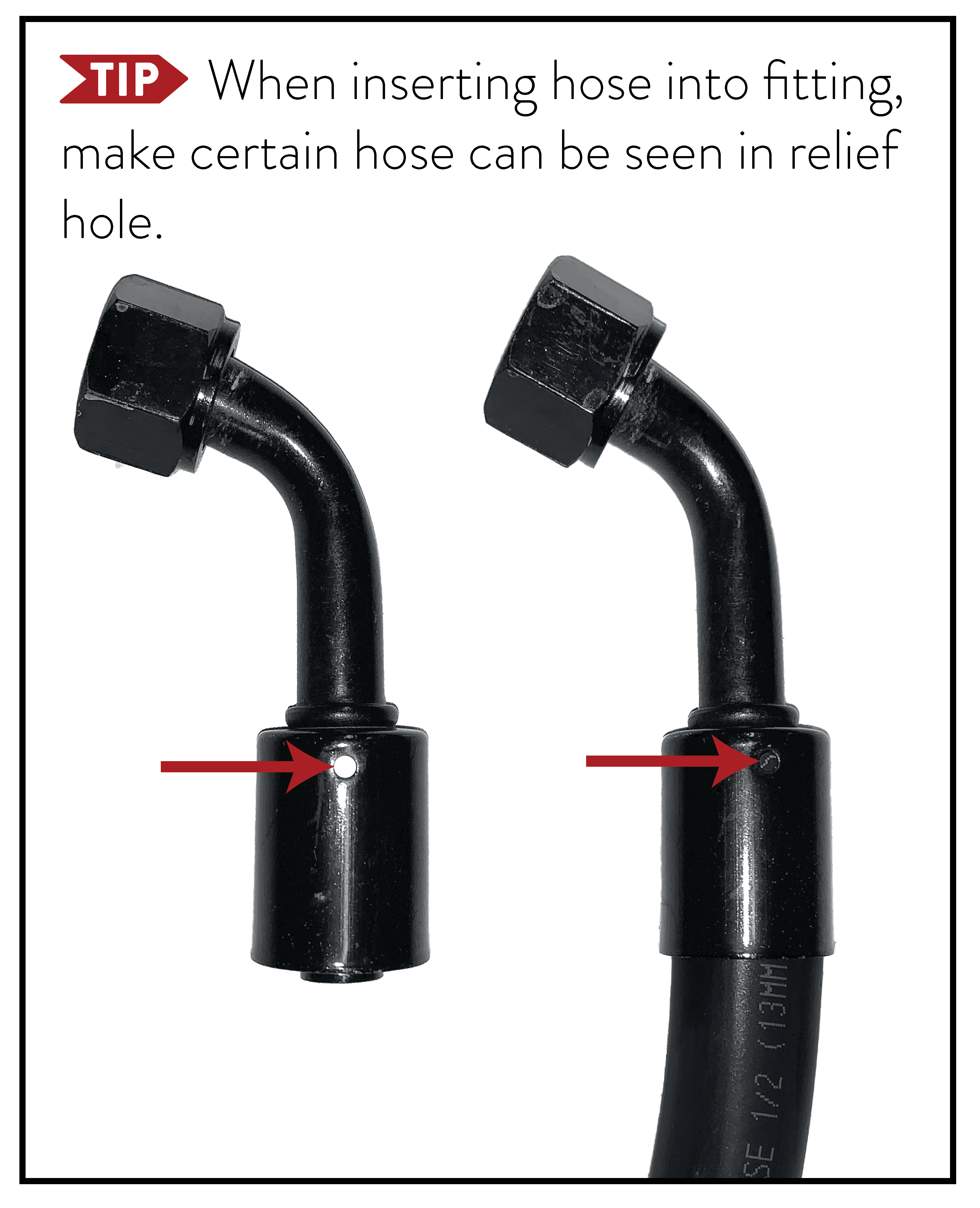
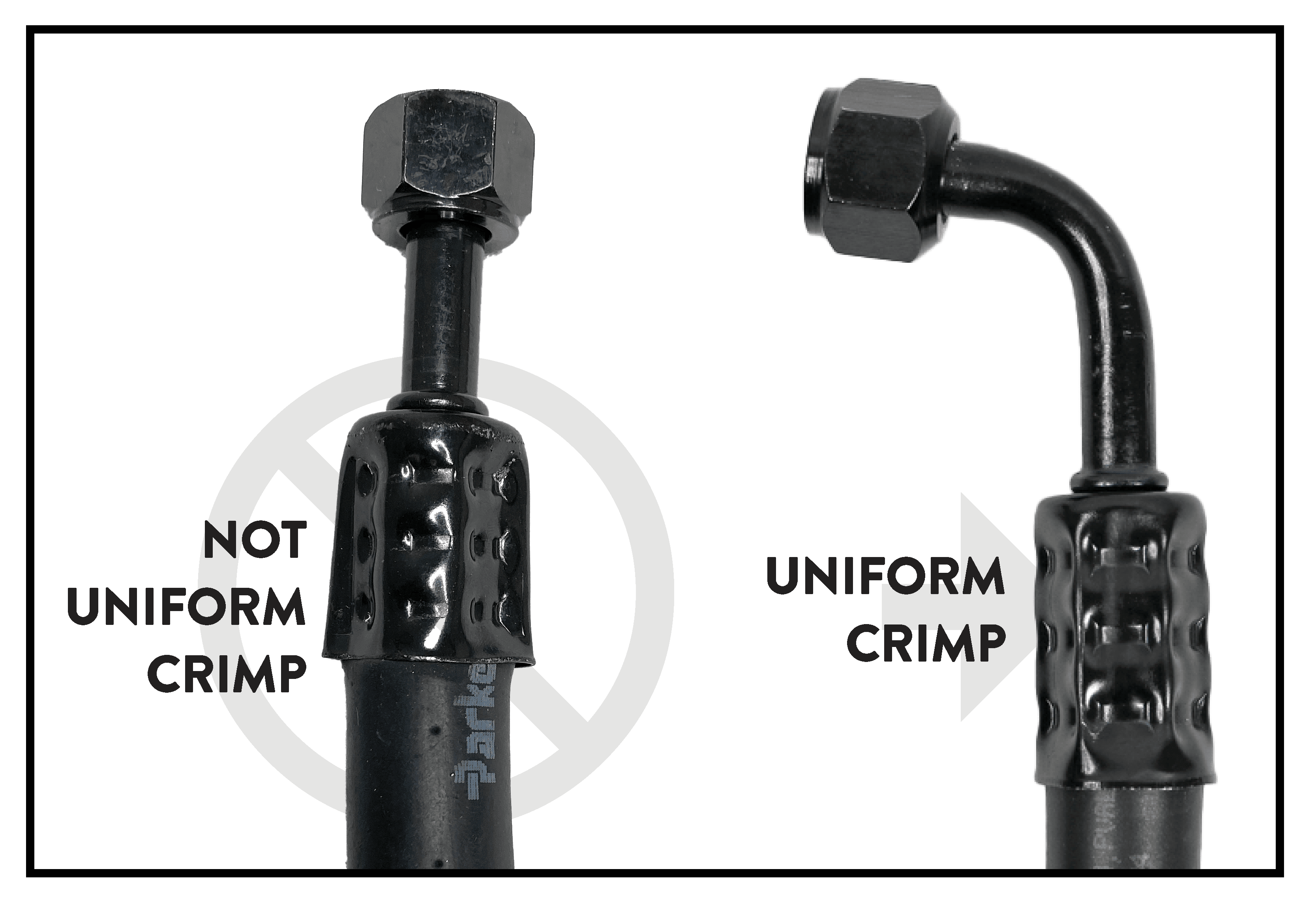
– hose fittings must be crimped by a reputable service center or can be sent back to us.
– hydraulic crimping cannot be used, automotive a/c crimping dies are only suitable for refrigerant barrier hoses.
CONDENSER BRACKETS
Use provided brackets or fab your own from mounting points. Secure condenser to minimize movement.
CONDENSER MOUNTING
Place condenser in front of radiator within 1”. Mount to radiator support with self tapping screws. Some condensers have mounting points on the top.

O-RINGS
When installing o-rings on the hose connections, be certain the o-ring is properly sealed. Also check for sharp edges on the seat. If installed wrong, or the seat has a sharp burr, the o-ring can be cut.
Use the o-ring pack supplied. Not all sizes and quantities will be used.
-
– Use 2 wrenches to tighten fittings.
-
– Do not over tighten.
-
– Use a few drops of mineral oil with every o-ring.
-
– Crushing or ripping an o-ring will create a small leak very difficult to locate.
PRESSURE SWITCH
DRIER
When removing caps, pressure will release. Do NOT leave drier open to air longer than a couple minutes. Mount drier in a location where the hoses can reach.
HOSE ROUTING
